In this project, I transform a basic, old, cheap PC ATX PSU into a bench-top power supply that can be used for doing electronics projects. All you need is an old ATX PSU, your soldering iron and some binding posts.
A bench-top power supply is an absolute must for any electronics hobbyist and enthusiast. However, sometimes, when just starting out, buying an adjustable power supply might be a bit expensive.
However, there is an easy, cheap and readily available option that many of us have lying around: an old PC ATX Power Supply. The modern ATX Power supply is made in such a way to provide 4 different very useful voltages: +5V, +3.3V, +12V and -12V.

The first step is to carefully disassemble the ATX Power supply after you have unplugged it and made sure that the capacitors are discharged.
You need to install binding posts to the front of the case by drilling out some holes and inserting the corresponding binding posts.
If you want, you can buy different coloured binding posts which correspond to the colour of the wiring inside the ATX power supply.
With the binding posts screwed in, cut to the required length the groups of wires that are of the same colour. Connect these to the binding posts and isolate with heat shrink tubing.

Modern ATX power supplies use different coloured wires for the different voltages. Below, you will find the colours of wires which correspond to the various voltages inside the ATX power supply.
Black – These wires connect to Ground (GND)
Red – These wires connect to +5V
Orange – These wires connect to +3.3V
Yellow – These wires connect to +12V
Blue – These wires connect to -12V
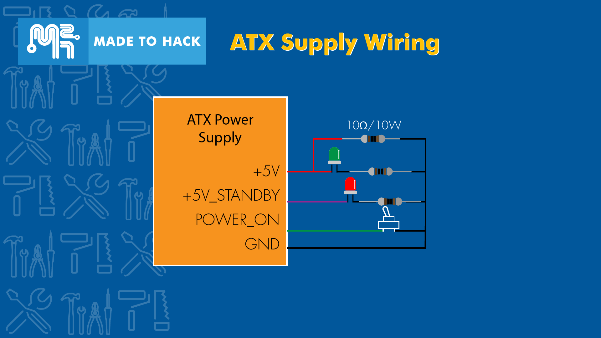
In order to be able to better control your bench-top power supply, we can add some switches and LEDs that will power on the voltages and give us a status.
When you connect mains power to your PSU, there is a status wire that turns on. This wire is +5V_STANDBY. In the ATX power supply, this wire is Purple.
I connect a RED LED with a resistor between this wire and GND. So when mains power is turned on to the PSU, the RED LED turns on.
To control the output to our binding posts, there is another wire called POWER_ON, which is a Green wire. A small power switch is connected between this Green POWER_ON wire and GND. When you flip this switch, power is turned on to the various voltages (and to your binding posts).
We can then connect a GREEN LED and a resistor between +5V and GND so that it turns on when POWER_ON is turned on. That way, we can tell that we have power coming out of our binding posts.
Finally, ATX Power supplies need a load on either the +5V or +12V so that it turns on. The easiest way to take care of this is to connect a 10 Ohm / 10 Watt resistor between +5V (Red wire) and GND. So that way, when we flip the POWER_ON switch, this will make sure the outputs are live.

Once everything is connected and the case is reassembled, it is time to test the output voltages. Flip the POWER_ON switch and make sure you are getting the output voltages from the ATX Power Supply. You now have a bench-top power supply you can use with a variety of useful voltges.
Latest Projects
- Epoxy Granite Vise - Emmas Toolmaking Competition 2018
- 350W Brushless DC Hover Board Wheel Motor
- Cleaning & Repairing New Old Stock Soviet Precision Level
- Made 2 Hack - Retro Intro
- Epoxy Granite / Epoxy Quartz Mixes and Tests
- Hackaday Prize 2018 Announcement
- Traditional Japanese Woodblock Print Framing
- How To Build a DIY SMD Reflow Oven
- Replacing Ball Bearings on Electric Induction Motors
- Electronics Workbench LED Lighting Upgrade