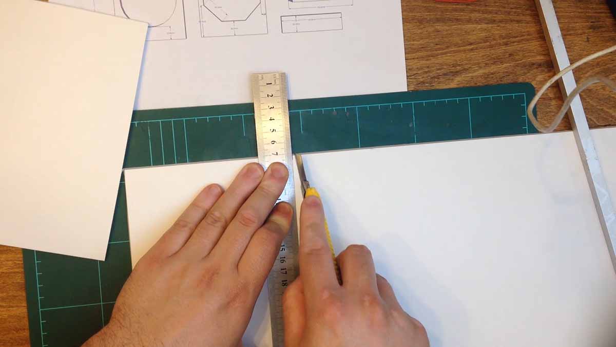
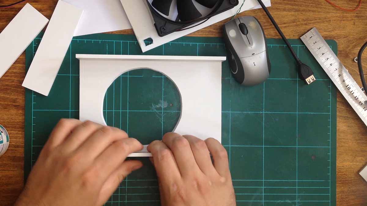
I begin by cutting 3mm thick PVC plastic sheets into the proper dimensions to make the box. The front panel will have a circle opening for the air to be pulled in.
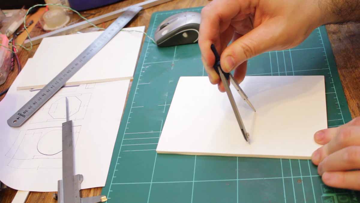
I cut this piece after measuring it with a compass. The back panel has a octagonal opening which will allow me to attach the fan to the back.
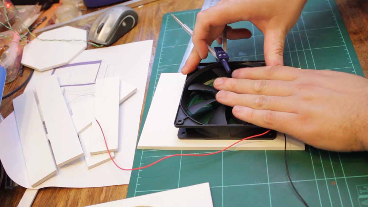
With the front panel cut, I dry fit the fan. I then drill the holes for the fan on the back panel. Once the fan was temporarily screwed in, I marked and cut out the hole for the power connector
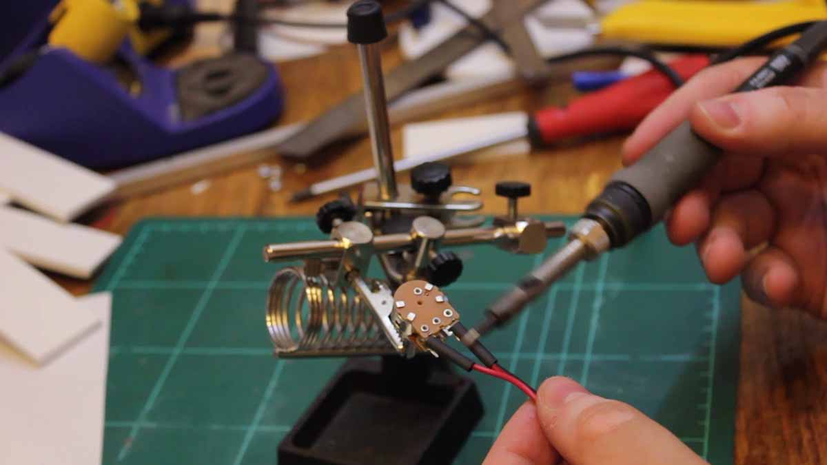
For this project, I used a potentiometer that has an integrated on off switch. I soldered it to the power connector and dried fit the potentiometer to the front panel
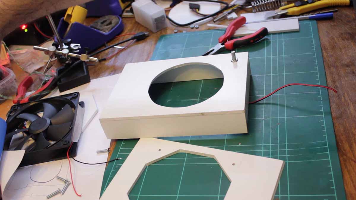
The side walls were then glued to the front panel. And then I glued the top and bottom walls. I drilled the hole for the potentiometer and the status LED on the front panel.
I soldered the electronics which will run the fan speed and the LED. Afterwards, I drilled some holes on the back panel which will allow me to screw it to the front assembly.
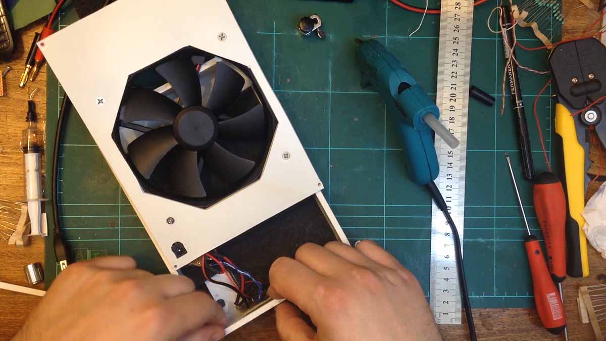
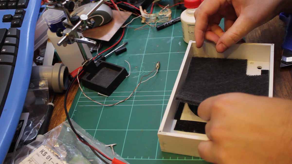
As before, I glued some velcro strips to the front panel and stuck on an activated carbon filter pad. I then began the final assembly by fitting the electronics and attaching the fan.
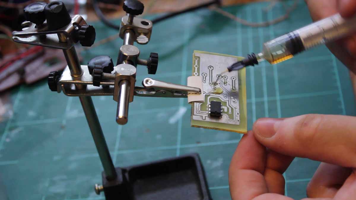
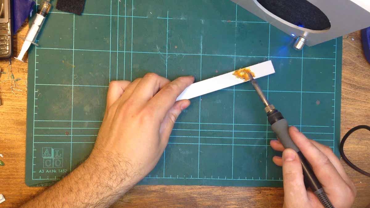
I used hot glue to stick everything in place. Finally, I tested the fume extractor as before by melting some solder flux.
The unit works fine however the simpler cardboard unit seems to be more powerful. Maybe because of the larger space between the fan and the filter.