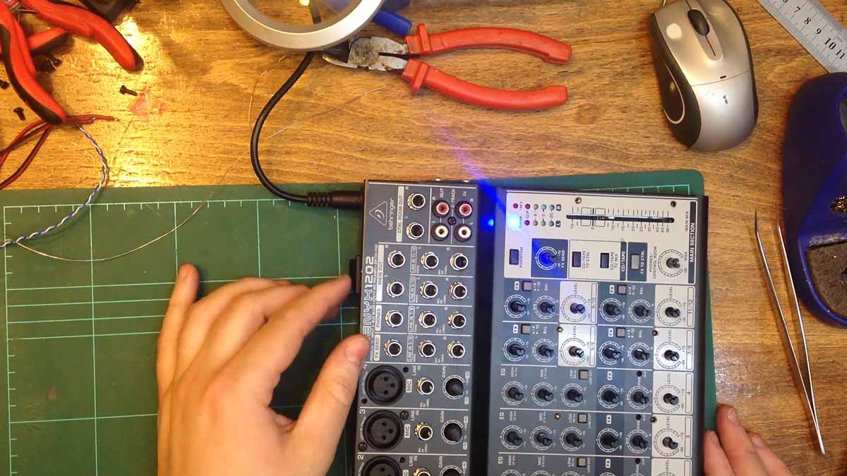
For my voice over work, I use a Xenyx 1202 4-channel mixer made by Behringer that doesn’t have a power switch. To power it on, the power cable from the transformer has to be inserted every time and unplugged to power the mixer off. This is rather annoying as I don’t understand why they didn’t add a switch when they designed the mixer.
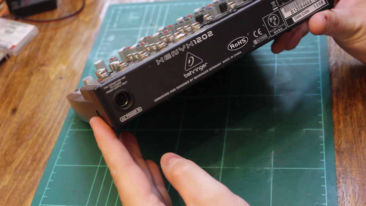
My idea is to add a power switch as close as possible to the power jack.
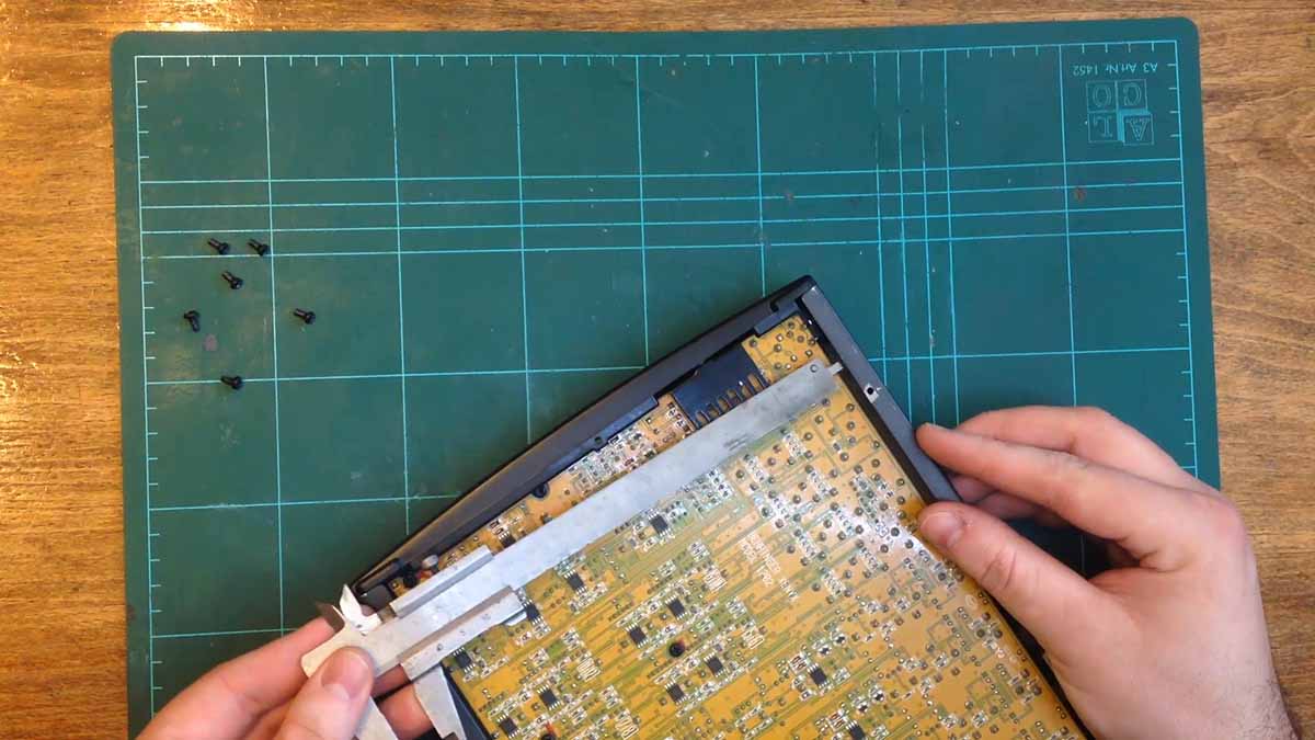
The first step is to disassemble the back of the unit and have a look at how the power is connected to the mixer. With the cover off, I measured the depth available from the edge of the PCB to the outside case.
I then measured the voltages with the power cable connected. The voltage that comes in is 36VAC that is center tapped to give two 18VAC rails. After consulting with some folks on the EEVBlog, I decided to connect a Double Pole Single Throw switch in between the two AC signals and leave the center tap alone.

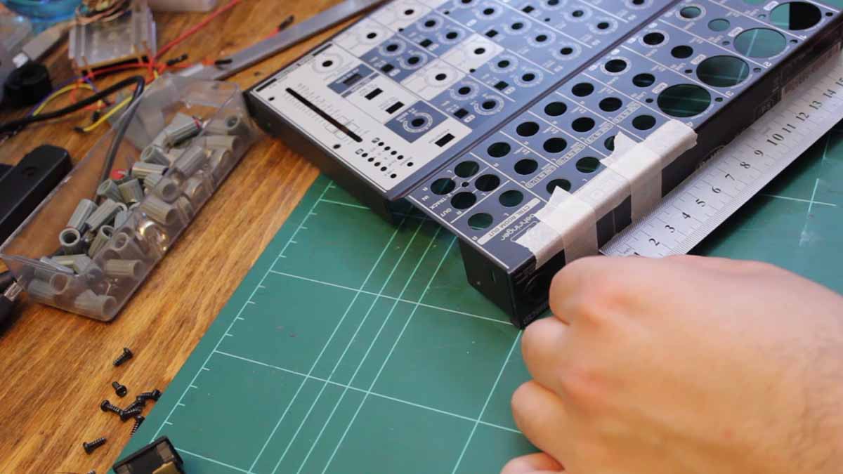
With the plan in place, it was time to disassemble the mixer completely. With the mixer disassembled, it was time to verify that the switch would fit in the position I wanted.

I then measured the position of the switch so I would know where to cut out a hole. With the measurements complete, I taped off the area so it would be easier to see the cutting.
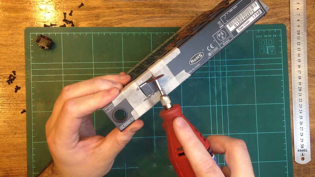
Using my rotary tool and a cutting disk, I made the cutout for the switch. I removed the bit of steel from the outer case with some pliers and a screwdriver. I then sanded the cutout with an abrasive stone and some hand files.
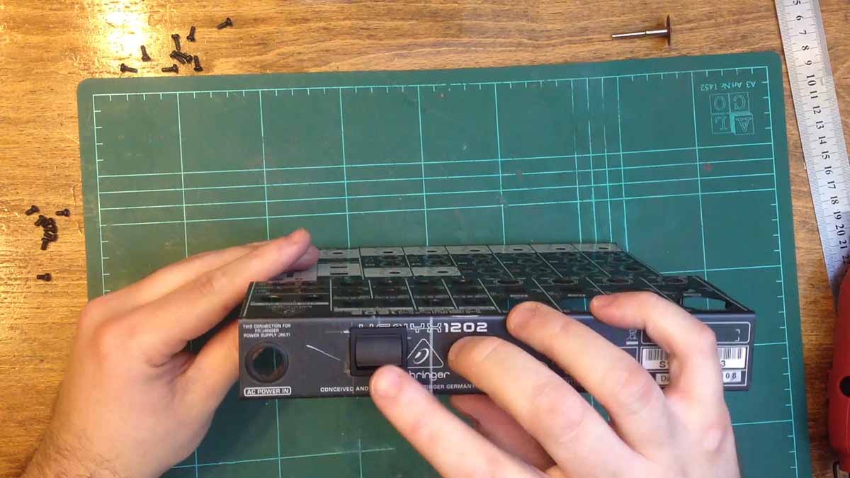
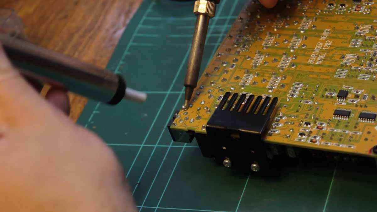
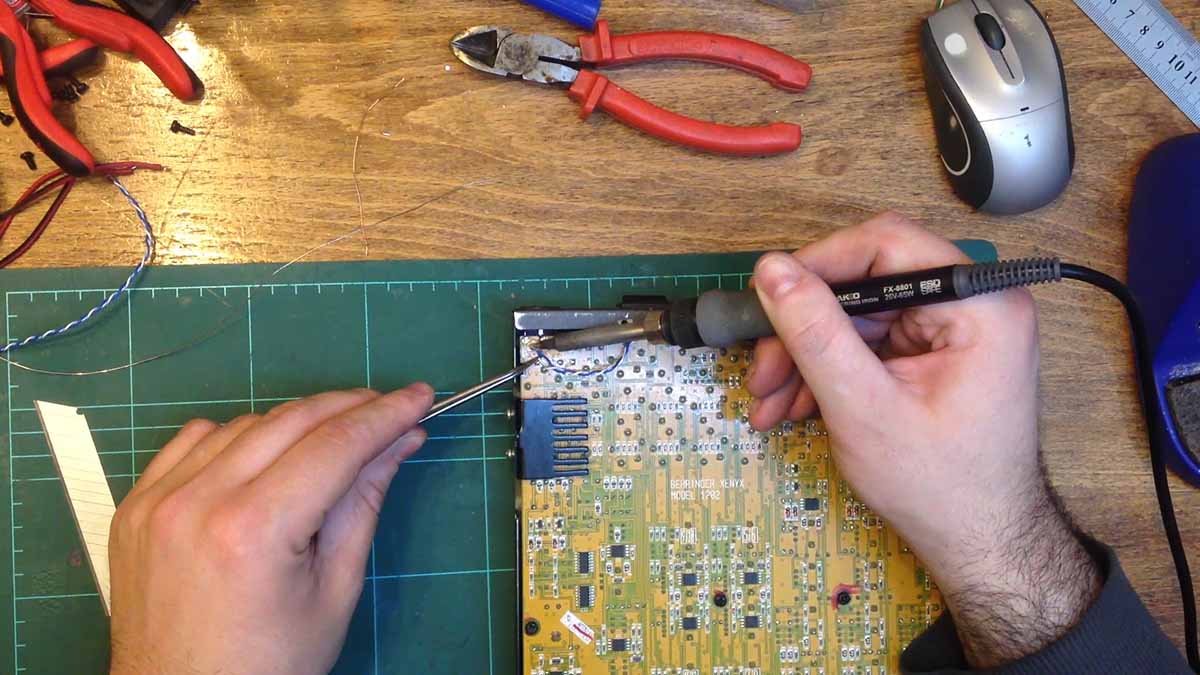
With the hole complete, it was time to dry fit the power switch. I soldered some temporary wires to the switch. It was now time to remove the PCB mounted power socket. This took a while as the socket has a heavy ground plane.
I then soldered the wires from the switch to the power socket. And then it was time to fit the pcb back into the case and screw it in with a few top screws to make sure everything fit.
Satisfied that all fit well, it was time to solder the power socket back to the PCB but without the power pins making contact. I then screwed back on a few more of the screws. With the top section screwed back on, I now connected the wires coming off the switch to the PCB where the socket used to make contact. I also put down some double sided tape to both insulate the wires and to stick them down.
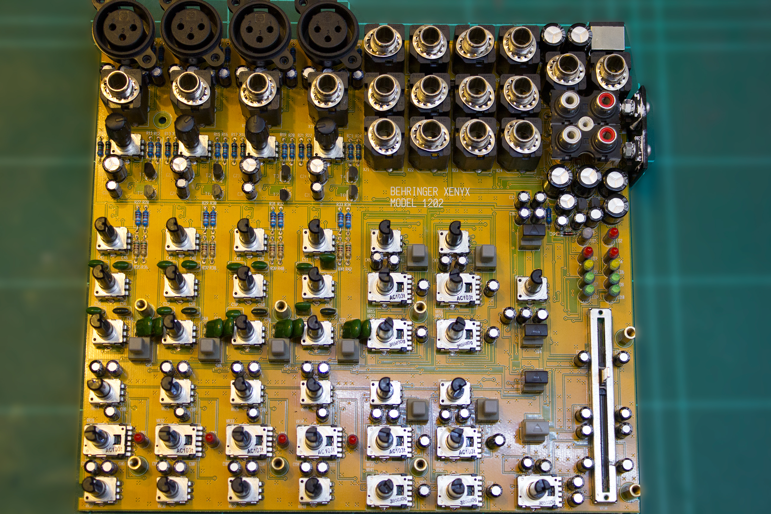
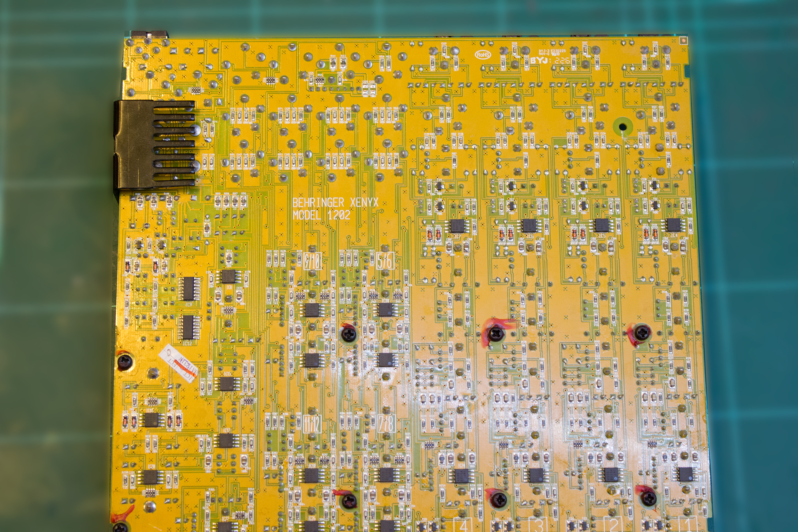
Xenyx 1202 High Resolution PCB Photos